
Related Posts
(1) Importance of Well Integrity in Aging Wells:
Well integrity is the application of technical, operational, and organizational solutions to reduce the risk of uncontrolled fluid release throughout a well’s lifecycle. In mature fields, aging wells pose unique integrity challenges due to:
Degradation of materials: Over time, casing, tubing, and wellheads can corrode, erode, or suffer mechanical fatigue.
Thermal and pressure cycling: Repeated cycles can lead to expansion and contraction of materials, weakening seals and connections.
Cement deterioration: The cement that isolates different formation layers may crack, shrink, or lose adhesion.
Formation compaction or subsidence: Alters stress distribution and causes deformation in well structures.
Maintaining integrity in these wells is crucial for:
Safety of personnel and environment: Preventing blowouts, leaks, and contamination.
Regulatory compliance: Governments and agencies impose strict well integrity rules.
Operational efficiency: Ensures reliable production and reduces costly shutdowns.
Asset value preservation: Extends well life and maximizes hydrocarbon recovery.

(2) Key Components of Well Integrity:
Effective well integrity depends on the performance and condition of several primary components throughout the life cycle of the well. These components act as barriers that prevent uncontrolled release of fluids, maintain wellbore stability, and ensure safe operations under varying conditions.
(a) Casing Strings:
Steel pipes installed in sections and cemented in place to maintain wellbore stability and isolate different subsurface zones.
Must provide long-term mechanical integrity and hydraulic isolation from formation fluids.
Designed to withstand formation pressures, thermal expansion, and load variations throughout drilling, production, and abandonment.
Types include conductor, surface, intermediate, and production casing.
(b) Tubing:
The inner conduit through which oil, gas, or other fluids are produced to the surface.
Isolates production fluids from casing, minimizing corrosion and wear on the casing.
Subject to corrosion, erosion, scaling, and pressure cycling, especially in wells with high CO₂ or H₂S content.
May include corrosion-resistant alloys (CRAs) and coated tubing for enhanced integrity.

(c) Cement Sheath:
A layer of cement pumped around casing strings to provide a seal between the casing and surrounding formation.
Prevents migration of formation fluids between zones (zonal isolation).
Supports the casing and contributes to wellbore structural integrity.
Must maintain bond strength over time despite shrinkage, debonding, or chemical degradation from formation fluids.
Integrity confirmed via tools like cement bond logs (CBL) and ultrasonic logs.
(d) Wellhead and Christmas Tree:
Surface pressure-containing components that support the casing and control the flow of fluids.
Wellhead supports casing strings and seals annular spaces.
Christmas Tree includes valves, spools, and fittings used to control production.
Forms a critical surface barrier, especially during high-pressure operations.
Includes annulus access ports, kill lines, and pressure gauges for monitoring and intervention.

(e) Annular Barriers:
Devices and systems used to seal the space (annulus) between casing and tubing.
Includes mechanical packers, cement, and annular pressure-operated valves.
Prevents crossflow between zones and pressure build-up in annular spaces.
Supports the two-barrier philosophy in well integrity design.
Regularly monitored for pressure anomalies, indicating possible seal failures.
(f) Control Systems:
Instrumentation and automation used to monitor well integrity in real-time.
Includes pressure sensors, temperature gauges, flow meters, and acoustic monitoring systems.
Detects anomalies such as sustained casing pressure (SCP), leaks, or unexpected temperature changes.
Enables rapid response and automated shut-in via surface-controlled subsurface safety valves (SCSSVs).
Part of both proactive surveillance and emergency response systems.

(3) Monitoring Techniques (Pressure Testing, Logging):
Well monitoring is essential to identify potential issues before they escalate into serious integrity failures. It allows for early detection of barrier degradation, leaks, corrosion, or unwanted pressure anomalies. Continuous and periodic surveillance helps maintain safe operation and extends the life of the well. Key techniques include:
(a) Pressure Testing:
Verifies the integrity of tubing, casing, wellhead, packers, and annular seals under expected operating conditions.
Positive Pressure Test: Applies pressure to the wellbore system (e.g., tubing or annulus) and observes whether it holds steady over time. Confirms seal tightness.
Negative Pressure Test: Reduces pressure in a closed system and monitors for an unexpected pressure rise, which may indicate fluid entry from formation or another wellbore section.
Common Scenarios:
After installation of completion equipment.
Before starting production or after interventions.
During casing installation to confirm cement sheath isolation.
Standards & Acceptance Criteria: Based on API RP 90, ISO 16530, and operator-specific guidelines.

(b) Well Logging:
Employs a variety of downhole tools to assess the condition and integrity of the well and its barriers.
Cement Bond Logs (CBL): Measure the acoustic response to evaluate bonding between casing, cement, and formation. Poor bond can indicate leak paths or lack of zonal isolation.
Temperature Logs: Identify abnormal temperature gradients, often caused by fluid movement behind casing or crossflow between zones.
Noise/Acoustic Logs: Use sensitive microphones to detect sounds of fluid movement, which may suggest casing leaks or flow behind pipe.
Caliper Logs: Measure the internal diameter of casing or tubing to detect mechanical deformation, scale buildup, corrosion, or wear.
Multi-Finger Imaging Tools: Provide detailed 3D imaging of casing interior to detect pitting, holes, or collapse.

(4) Tools and Equipment Used for Well Integrity Interventions:
When well integrity issues are detected such as leaks, pressure anomalies, or mechanical failures diagnostic and remedial interventions become critical. These require specialized tools and equipment that allow safe and efficient operations, often under live-well (pressurized) conditions.
(a) Wireline and Slickline Tools:
Used to deploy and retrieve equipment or run diagnostic tools inside the wellbore.
Wireline tools (electric) that used for logging, perforation, setting retrievable plugs, and measuring downhole parameters.
Slickline tools (non-electric) that deployed for mechanical operations like setting or retrieving valves, plugs, or memory gauges.
Tools include bridge plugs, retrievable packers, junk baskets, and fishing tools.
(b) Coiled Tubing Units (CTU):
Flexible steel tubing injected into the well while under pressure.
Ideal for live-well interventions without killing the well.
Can used in chemical treatments, cleanouts, acidizing, sand removal, plug milling, and jetting operations.
Enables operations at depth where conventional tubing would be impractical.

(c) Cementing Units:
Mobile or skid-mounted systems used to mix and pump cement into the well.
Used in squeeze cementing to seal off leaking annuli, repair poor cement behind casing, or abandon perforated intervals.
Equipped with high-pressure pumps, cement blenders, and displacement tanks.
(d) Packer Systems:
Mechanical or hydraulic tools used to isolate well sections or create pressure barriers.
Types include permanent, retrievable, hydraulic-set, and inflatable packers.
Used for zonal isolation, casing leak remediation, and pressure testing individual intervals.
Critical in dual-barrier configurations during well workovers or recompletions.
(g) Surface Pressure Control Equipment:
Critical for safely managing well pressure during interventions.
Blowout Preventers (BOPs): Provide shut-in capability in case of unexpected flow.
Lubricators: Allow safe deployment of slickline or wireline tools into live wells.
Wellhead isolation tools, grease injection systems, and quick-connect pressure control heads are also used.
Essential for well control, especially in high-pressure/high-temperature (HPHT) environments.

(5) Regulatory Requirements and Industry Standards:
Well integrity must meet both national regulations and international best practices to ensure safety, compliance, and performance:
(a) National Regulations:
Vary by country but often include:
Mandatory pressure tests and well integrity logs.
Proper documentation and reporting.
Barrier acceptance criteria.
Regular inspection schedules.
(b) International Standards:
API RP 90: Provides guidance on annular pressure management and well integrity.
ISO 16530-1: Establishes a framework for managing well integrity throughout the lifecycle of a well.
NORSOK D-010 (Norway): A widely respected standard for well integrity.
(c) Operator-Specific Policies:
Many companies enforce stricter internal guidelines, including:
Minimum barrier standards.
Enhanced well surveillance and data analysis.
Detailed well integrity manuals.
(6) Common Failure Modes and Mitigation Strategies:
Well integrity can be compromised by a variety of failure modes throughout a well’s life cycle. Recognizing these failures early and applying effective mitigation strategies is critical to ensuring the safety, reliability, and regulatory compliance of oil and gas operations.
(a) Corrosion (Internal/External):
Cause:
Exposure to corrosive environments e.g., formation water, CO₂, H₂S, chlorides, or injected fluids.
Mitigation Strategies:
Use of corrosion-resistant alloys (CRAs) or coated tubulars.
Chemical injection of corrosion inhibitors.
Cathodic protection systems for external casing corrosion.
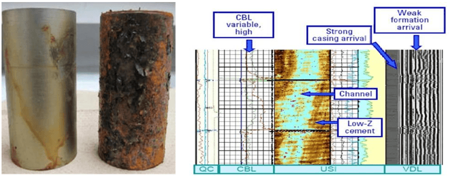
(c) Poor Cement Bond / Channeling:
Cause:
Inadequate mud removal, poor displacement, or improper cement design causing unbonded zones or fluid channeling.
Mitigation Strategies:
Cement evaluation logs (CBL, VDL, ultrasonic imaging) to assess bond quality.
Remedial cementing (squeeze jobs) to seal off leaking zones.
(d) Tubing Leaks or Failures:
Cause:
Corrosion such as: galvanic or pitting corrosion, erosion from high-velocity fluids, mechanical wear, or scaling causing pitting and thinning.
Mitigation Strategies:
Tubing inspection via caliper logs or ultrasonic tools.
Tubing replacement during workover.
Use of chemical inhibitors and scale management programs.
Deployment of retrievable SCSSVs to isolate leaking zones.
(e) Casing Collapse or Buckling:
Cause:
External formation pressure exceeds casing resistance, or poor cement bonding leads to unsupported casing.
Mitigation Strategies:
Casing patches, expandable liners, or mechanical sleeves.
Sidetracking the wellbore to bypass the damaged zone.
Preventive design use correct casing grade, weight, and centralization.

(f) Seal Failures in Wellhead or Packoff:
Cause:
Aging elastomers, pressure cycling, corrosion, or installation errors lead to leaking seals.
Mitigation Strategies:
Routine seal inspections and pressure testing.
Seal replacement with high-performance elastomers or metal-to-metal seals.
Upgrading wellhead equipment to modern integrity standards.
(g) Mechanical Failures (Valves, Packers, Safety Devices):
Cause:
Wear and tear, poor maintenance, installation errors, or fatigue in components such as SSSVs, packers, or valves.
Mitigation Strategies:
Regular function testing and inspection during scheduled maintenance.
Component replacement with higher-specification alternatives.
Use of reliable setting tools and installation procedures.
Redundant safety devices in high-risk wells (e.g., dual packers, dual SCSSVs).


