


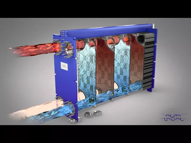
Heat Exchangers: Principles, Design, and Applications in the Petroleum Industry
Related Posts
Definition
A heat exchanger is a mechanical device designed to transfer thermal energy between two or more fluids at different temperatures while preventing direct contact between them. It enables efficient energy utilization and heat recovery across industrial processes, particularly in systems where temperature regulation is critical for performance and safety.
Heat Transfer Mechanisms
Conduction
Definition:
Conduction is the process by which thermal energy is transmitted through a solid or stationary medium due to a temperature gradient, without any bulk movement of the material itself.
It occurs as energetic particles (atoms, ions, or electrons) in regions of higher temperature transfer their energy to neighboring particles at lower energy levels through molecular interaction or electron diffusion.
Example:
In a metal wall separating two fluids at different temperatures, heat is transferred through the wall thickness purely by conduction. Materials with higher kkk, such as copper and aluminum, are efficient conductors, while materials like ceramics and plastics act as insulators.
(Reference: Cengel & Ghajar, 2020; Incropera et al., 2017)

Convection
Definition:
Convection is the mode of heat transfer that occurs between a solid surface and an adjacent fluid (liquid or gas) that is in motion. It involves the combined effects of energy conduction within the fluid and bulk fluid motion, which transports energy from one region to another.
Types of Convection:
Natural (Free) Convection: Caused by density differences resulting from temperature variations within the fluid (e.g., air rising above a hot surface).
Forced Convection: Occurs when a fluid is forced to flow over a surface by an external means such as a pump or fan.
Example:
In a shell-and-tube heat exchanger, convection dominates the heat transfer between the tube wall and the moving fluids on both sides — forced convection on both shell and tube sides enhances overall efficiency.
(Reference: Incropera et al., 2017; Bejan, 2013)

Main components of heat exchangers

Tube:
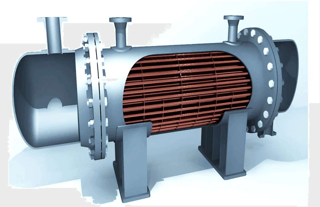
In shell-and-tube heat exchangers, the tubes serve as the primary surfaces for heat transfer between the fluids flowing inside and outside the tube bundle. They are typically fabricated by welding, extrusion, or seamless drawing to ensure structural integrity under varying pressure and temperature conditions.
Common construction materials include carbon steel, stainless steel, copper, titanium, and Inconel, chosen based on the process fluid’s corrosiveness, thermal conductivity, and mechanical strength. According to TEMA standards, tube diameters in compact heat exchangers generally range between 0.625 inch (16 mm) and 1.0 inch (25 mm), offering a balance between heat transfer area, mechanical stability, and flow resistance.
The tube wall thickness is selected based on design parameters such as internal pressure, thermal stress, corrosion allowance, and allowable stress limits of the material. Typical tube lengths vary from 6 to 24 feet (approximately 2 to 7 meters), depending on exchanger capacity and layout requirements. However, increasing tube length can reduce the overall shell diameter but may also lead to higher shell-side pressure drops due to extended flow paths and increased frictional resistance.
Shell:
The shell of a shell-and-tube heat exchanger serves as the primary pressure boundary enclosing the tube bundle and directing the flow of the shell-side fluid. It is typically fabricated from seamless or welded steel pipes or rolled metal plates, depending on the exchanger size, design pressure, and fabrication method.
Shell materials are selected to withstand high operating pressures and temperatures, as well as to provide resistance to corrosion, erosion, and thermal fatigue resulting from prolonged service in harsh industrial environments. Common materials include carbon steel, stainless steel, and alloy steels, while more specialized applications may employ titanium or nickel-based alloys for superior corrosion resistance.
The inner geometry of the shell must maintain a perfectly circular and uniform diameter along its length to ensure proper alignment of the baffles and to minimize bypassing or dead zones in the shell-side flow. Maintaining dimensional accuracy reduces the clearance between the baffle edges and the shell wall, which improves flow distribution, enhances heat transfer performance, and reduces the likelihood of flow-induced vibration.

Tube sheets:
The tube sheet is a thick, perforated metal plate that serves as a structural support and sealing interface for the tubes within a shell-and-tube heat exchanger. Each tube passes through a precisely machined hole in the tube sheet, where it is either expanded, welded, or both, to ensure mechanical stability and leak-tight sealing between the tube-side and shell-side fluids.
Tube sheets are typically fabricated from materials such as carbon steel, stainless steel, or corrosion-resistant alloys, selected based on operating temperature, pressure, and the corrosive nature of the fluids. In high-temperature or high-pressure applications, the tube sheet must comply with ASME Section VIII design requirements to withstand differential expansion and mechanical stresses.
The tube sheet arrangement defines the exchanger’s mechanical layout — with one sheet located at each end of the tube bundle. The shell extends beyond these tube sheets and is sealed using channel heads or bonnets, thereby forming enclosed chambers that isolate the shell-side and tube-side flows. Proper tube sheet alignment and surface finish are critical to maintaining tight tolerances, ensuring efficient heat transfer, and preventing leakage or vibration during operation.

Channels or Heads:
The channel (also referred to as the head) is the front-end component of a shell-and-tube heat exchanger that encloses the tube bundle and directs the tube-side fluid into and out of the exchanger. It also serves as a pressure boundary for the tube-side flow, ensuring both mechanical strength and hydraulic efficiency.The type and configuration of the channel depend primarily on the operating conditions, maintenance requirements, and process design. According to the TEMA classification, several channel types are used:
Bonnet-type (integral) heads: These are permanently attached to the tube sheet, either welded or bolted, and are commonly applied where the internal inspection or cleaning of the tube side is infrequent. This design offers compactness, simplicity, and reduced leakage potential.
Removable cover channels: Used in systems requiring periodic maintenance or tube inspection. The cover is bolted or flanged to the channel body, allowing easy disassembly without disturbing the shell-side connections.
Split-ring or flanged-and-dished heads: Applied in large exchangers or high-pressure systems where quick access is required while maintaining robust sealing performance.
For applications that involve frequent inspection, cleaning, or replacement of the tube bundle, removable channel covers are preferred to ensure ease of maintenance and extended service life of the exchanger.
Proper material selection for channel components follows ASME Section VIII and TEMA guidelines, taking into account pressure containment, corrosion resistance, and thermal compatibility with other exchanger parts.

5. Tube Pitch
The tube pitch refers to the center-to-center distance between adjacent tubes in a shell-and-tube heat exchanger. It is a fundamental geometric parameter that directly influences thermal performance, mechanical strength, ease of maintenance, and flow distribution on the shell side.
According to TEMA standards, the minimum tube pitch is generally 1.25 times the outer tube diameter, ensuring adequate spacing for tube installation, expansion, and effective cleaning. The arrangement of the tubes follows specific geometric patterns that optimize heat transfer and hydraulic characteristics. The most common layouts include:
Triangular pitch (30° or 60°): Provides the highest heat transfer area per unit volume and promotes greater turbulence, enhancing the overall heat transfer coefficient. However, this configuration is more difficult to clean mechanically due to restricted access between tubes.
Square pitch (90°): Facilitates easier mechanical cleaning and maintenance since straight-line access is available between adjacent tubes. It is commonly used when fouling is expected or when periodic cleaning is required.
Rotated square (45°) pitch: Offers a compromise between the high heat transfer of triangular arrangements and the accessibility of square pitches, allowing improved vapor flow and reduced pressure drop.
In vertical exchangers or systems involving two-phase flow, the square pitch configuration is often preferred, as it allows vapors to rise freely between tubes, minimizing vapor entrapment and promoting uniform phase distribution.
Optimizing the tube pitch is essential for balancing thermal efficiency, pressure drop, mechanical stability, and cleanability, thereby achieving the best possible performance for a given design.

6. Baffles:
Baffles are internal flow-directing components installed within the shell of a shell-and-tube heat exchanger. Their primary function is to guide and control the shell-side fluid flow, forcing it to move transversely across the tube bundle rather than following a straight path along the shell. This redirection of flow increases fluid velocity and turbulence, resulting in an enhanced convective heat transfer coefficient and improved overall thermal performance.
In addition to promoting effective heat transfer, baffles play a crucial mechanical support role, holding the tubes firmly in position to prevent vibration, sagging, or mechanical fatigue caused by fluid-induced forces or thermal expansion. Proper baffle spacing and design are essential to maintain structural stability and minimize vibration-related tube damage, especially in large horizontal exchangers.
The use of baffles also contributes to the reduction of fouling, a phenomenon characterized by the accumulation of unwanted deposits on the heat transfer surfaces. By increasing fluid turbulence, baffles reduce boundary layer thickness and mitigate the settling of particulate matter or the adhesion of deposits, which would otherwise increase thermal resistance and decrease exchanger efficiency.
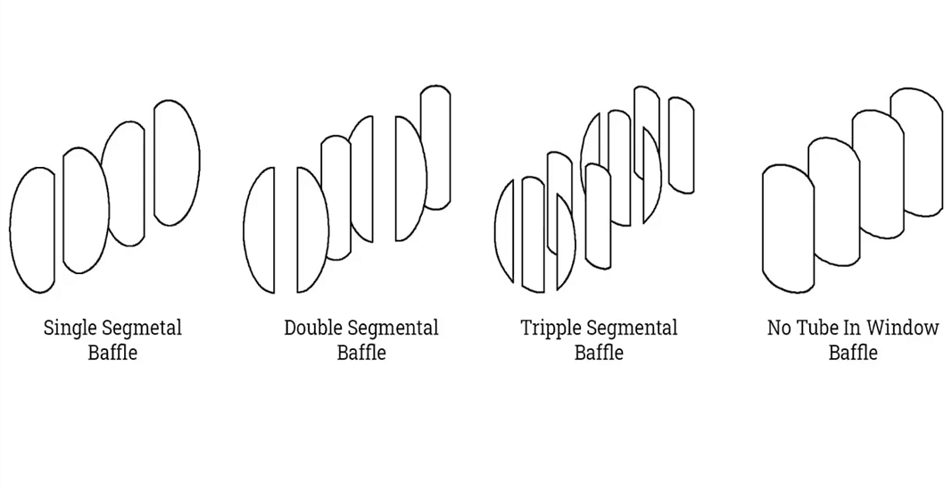
Several types of baffles are employed depending on the process requirements:
Segmental baffles (single or double): Commonly used to achieve cross-flow patterns and enhance turbulence.
Disk-and-doughnut baffles: Promote longitudinal flow with reduced pressure drop.
Helical baffles: Provide a continuous helical flow path that balances high heat transfer rates with low pressure losses.
The design parameters — such as baffle cut, spacing, and orientation — are optimized according to TEMA and ASME standards to achieve the desired trade-off between heat transfer enhancement, pressure drop, and mechanical reliability.
How Do Heat Exchangers Work
Flow Types
Part of the classification process for shell and tube heat exchangers is dividing them into groups using their characteristics for easier understanding of their function and operation. One of the characteristics used to group them is their flow type.
The three flow types of shell and tube heat exchangers are parallel, counter, and cross. The design, operation, and applications necessitate the three flow types be used in combinations.
Parallel flow is when the shell and tube sides enter the heat exchanger at the same end and flow directly to the opposite end. The temperature change is the same for each fluid and increases or reduces by the same amount.
Counter flow is when the fluids are flowing in opposite directions, enter the heat exchanger at opposite ends, and discharge at opposite ends. The counter flow is the most popular and efficient type of heat exchanger.
In a cross flow shell and tube heat exchanger, the fluids flow perpendicular to each other at a 90o angle. One of the fluids in a cross heat exchanger changes state (just as in a steam system condenser where cooling water absorbs the steam), then is absorbed by the fluid that has remained in its liquid state.

Types of Heat Exchangers and Applications
Double Tube Heat Exchangers:
A double-tube heat exchanger (also called a tube-in-tube heat exchanger) is one of the simplest and most fundamental types of heat exchangers. It consists of two concentric tubes — an inner tube and an outer tube (or shell) — forming a “pipe within a pipe” configuration.
Construction and Flow Arrangement
In this design, one fluid flows through the inner tube, while the second fluid flows through the annular space between the inner and outer tubes. This configuration enables efficient heat exchange between the two fluids separated by the tube wall, preventing physical mixing while allowing thermal energy transfer through conduction and convection.
Depending on process requirements, the fluids may flow in either:
Parallel flow (co-current): both fluids move in the same direction; or
Counter flow: fluids move in opposite directions, which typically yields a higher overall heat transfer efficiency due to maintaining a larger temperature difference along the length of the exchanger.
Operating Principle
The mechanism of heat transfer in double-tube exchangers involves two main steps:
Convection between the hot or cold fluid and the tube wall on each side.
Conduction through the wall material that separates the two fluids.
Advantages and Applications
Double-tube heat exchangers are valued for their simplicity, ease of maintenance, and cost-effectiveness. Because of their compact design and small diameter, they are ideal for installations in restricted spaces or for small-to-medium capacity processes. Their modular structure allows for series or parallel connections to achieve the desired heat transfer area or flow rate.
Typical applications include:
Cooling or heating of process fluids in chemical, food processing, and pharmaceutical industries.
Oil and gas operations for preheating or cooling lubricants and hydraulic fluids.
Pilot-scale systems or laboratory setups where flexible configurations are needed.
Design Flexibility
The compactness and linear geometry of the double-tube exchanger allow engineers to arrange multiple units in series (to increase heat transfer surface area) or in parallel (to accommodate higher flow rates). This adaptability offers considerable layout flexibility in manufacturing plants or process systems with limited space.
However, despite their simplicity, double-tube exchangers are typically suited for low to moderate heat duties and smaller flow capacities compared with larger types such as shell-and-tube or plate heat exchangers.
Plate Heat Exchangers
A plate heat exchanger (PHE) differs fundamentally from traditional tubular designs such as double-tube or shell-and-tube exchangers. Instead of concentric pipes, this type employs a series of thin, corrugated metal plates to facilitate heat transfer between two fluids. The fluids flow in alternate channels formed between adjacent plates, separated by gaskets or brazed joints that prevent mixing while allowing efficient thermal contact.


